








Benefits of load balancing LDAP Servers
Load balancing Lightweight Directory Access Protocol (LDAP) provides the benefits of High Availability, improved performance and scalability:
- High availability (HA): Load balancing prevents the LDAP service from becoming a single point of failure. By distributing client requests across multiple LDAP servers, if one server fails (due to hardware issues, maintenance, or software problems), the load balancer automatically redirects traffic to the remaining healthy servers. This automatic failover process ensures that applications and users relying on the directory service maintain uninterrupted access to authentication and authorization services, which is critical for business continuity. It also allows administrators to take individual LDAP servers offline for maintenance, upgrades, or patching without impacting service availability.
- Optimal performance: Load balancing ensures efficient utilization of the LDAP server resources available. It distributes the load (like searches, binds, and updates) across the available server pool, preventing any single server from becoming a bottleneck and ensuring faster response times for client requests. Load balancing algorithms (e.g., Least Connections) can intelligently direct traffic to the server that is currently least busy, optimizing the use of all resources.
- Scalability: When demand increases, it’s possible to easily add new LDAP servers to the pool. The load balancer automatically incorporates them and starts distributing traffic, allowing the service to scale horizontally to handle increased user and application traffic.
About LDAP
LDAP (Lightweight Directory Access Protocol) is an open, cross-platform application protocol. It is designed to allow information to be shared regarding hosts, users, DNS, certificates, printers, and more in a network. A commonly used implementation is OpenLDAP, as well as Microsoft Active Directory which features LDAP support. LDAP can also be used with Kerberos to provide authentication services.
Why Loadbalancer.org for LDAP Servers?
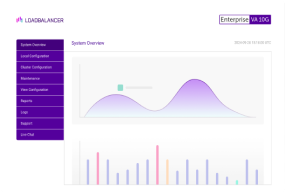
Loadbalancer’s intuitive Enterprise Application Delivery Controller (ADC) is designed to save time and money with a clever, not complex, WebUI.
Easily configure, deploy, manage, and maintain our Enterprise load balancer, reducing complexity and the risk of human error. For a difference you can see in just minutes.
And with WAF and GSLB included straight out-of-the-box, there’s no hidden costs, so the prices you see on our website are fully transparent.
More on what’s possible with Loadbalancer.org.
How to load balance LDAP Servers
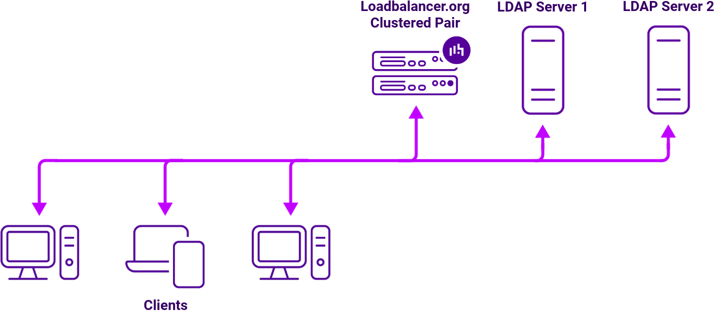
Loadbalancer.org appliances can be used in conjunction with a cluster of LDAP servers to provide a highly available LDAP service. Using load balancers also makes LDAP server maintenance easier, as well as making the service scalable should additional servers need to be added in the future to increase capacity.
| Protocol | Role | Default Ports | Supported load balancing methods |
|---|---|---|---|
| TCP/UCP/LDAP | For LDAP communication | 389 (or 3268 for Global Catalog access on a Microsoft AD server) | Layer 4 DR, Layer 4 NAT, Layer 7 TCP |
| TCP/UDP/LDAPS (“LDAP over SSL”) | For LDAP communication using TLS/SSL | 636 (or 3269 for Global Catalog access over TLS/SSL on a Microsoft AD server) | Layer 4 DR, Layer 4 NAT, Layer 7 TCP |
Example deployment: Microsoft LDAP
The load balancer can be deployed in 4 fundamental ways: Layer 4 DR mode, Layer 4 NAT mode, Layer 4 SNAT mode, and Layer 7 Reverse Proxy (Layer 7 SNAT mode).
For Microsoft LDAP, Layer 4 DR mode, Layer 4 NAT mode and Layer 7 Reverse Proxy are recommended.
Virtual service (VIP) requirements
The load balancer supports three deployment modes for Microsoft LDAP. Only one mode is required – select the mode that best suits your network topology (for more details of each mode, see Load Balancer Deployment Methods). Each mode uses a single VIP that load balances both LDAP and LDAPS:
| Ref. | VIP Name | Mode | Port(s) | Persistence Mode | Health Check | Topology |
|---|---|---|---|---|---|---|
| Mode 1 | Microsoft_LDAP | L4 DR (TCP) | 389,636 | Source IP (300s) | Connect to Port | One-Arm |
| Mode 2 | Microsoft_LDAP | L4 NAT (TCP) | 389,636 | Source IP (300s) | Connect to Port | Two-Arm |
| Mode 3 | Microsoft_LDAP | L7 Reverse Proxy (TCP) | 389,636 | Source IP (300s) | Connect to Port | One-Arm or Two-Arm |
For more on one- and two-arm topology, refer to the Topologies & Load Balancing Methods section of the Enterprise Admin Manual.
Deployment concept
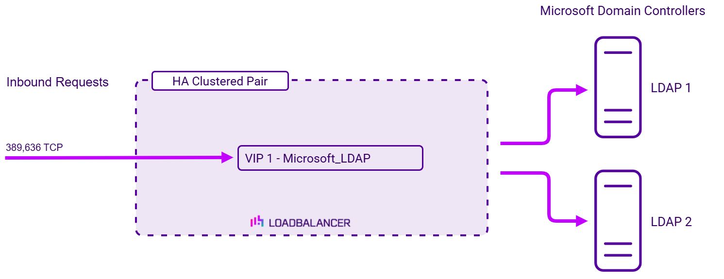
Once the load balancer is deployed, clients connect to the Virtual Service (VIP) rather than connecting directly to one of the Microsoft LDAP servers. These connections are then load balanced across the Active Directory Domain Controllers to distribute the load according to the load balancing algorithm selected:
For step-by-step deployment instructions for Layer 4 DR, Layer 4 NAT, and Layer 7 Reverse Proxy refer to our detailed Microsoft LDAP deployment guide.
About Layer 4 DR mode
One-arm direct routing (DR) mode is a very high-performance solution that requires little change to your existing infrastructure.
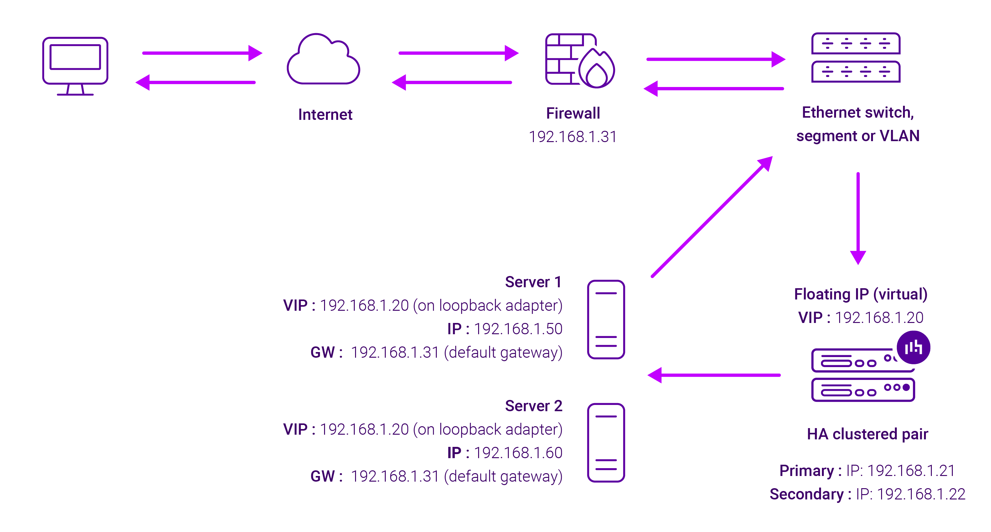
DR mode works by changing the destination MAC address of the incoming packet to match the selected Real Server on the fly which is very fast.
When the packet reaches the Real Server it expects the Real Server to own the Virtual Services IP address (VIP). This means that you need to ensure that the Real Server (and the load balanced application) respond to both the Real Server’s own IP address and the VIP.
The Real Servers should not respond to ARP requests for the VIP. Only the load balancer should do this. Configuring the Real Servers in this way is referred to as Solving the ARP problem.
On average, DR mode is 8 times quicker than NAT for HTTP, 50 times quicker for Terminal Services and much, much faster for streaming media or FTP.
The load balancer must have an Interface in the same subnet as the Real Servers to ensure Layer 2 connectivity required for DR mode to work.
The VIP can be brought up on the same subnet as the Real Servers, or on a different subnet provided that the load balancer has an interface in that subnet.
Port translation is not possible with DR mode, e.g. VIP:80 → RIP:8080 is not supported. DR mode is transparent, i.e. the Real Server will see the source IP address of the client.
About Layer 4 NAT mode
This mode is a high performance solution, although not as fast as DR mode. It requires the implementation of a two-arm infrastructure with an internal and external subnet to carry out the translation (the same way a firewall works). Also, each Real Server must use the load balancer as the default gateway. Layer 4 NAT mode is transparent, i.e. the Real Servers will see the source IP address of the client.
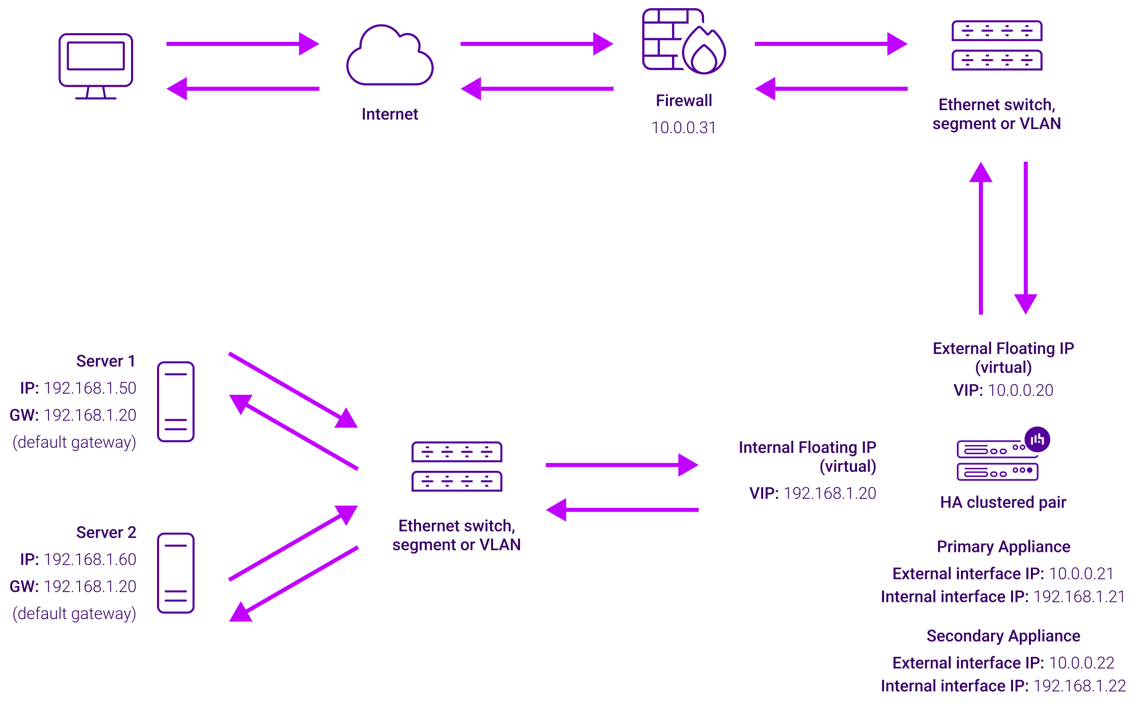
The load balancer translates all requests from the Virtual Service to the Real Servers. NAT mode can be deployed in two-arm (using 2 interfaces), or one-arm (using 1 interface). If you want Real Servers to be accessible on their own IP address for non-load balanced services, e.g. RDP, you will need to setup individual SNAT and DNAT firewall script rules for each Real Server or add additional VIPs for this. Port translation is possible with Layer 4 NAT mode, e.g. VIP:80 → RIP:8080 is supported. NAT mode is transparent i.e. the Real Servers will see the source IP address of the client.
About Layer 7 Reverse Proxy mode
Layer 7 Reverse Proxy uses a proxy (HAProxy) at the application layer. Inbound requests are terminated on the load balancer and HAProxy generates a new corresponding request to the chosen Real Server. As a result, Layer 7 is typically not as fast as the Layer 4 methods. Layer 7 is typically chosen when either enhanced options such as SSL termination, cookie based persistence, URL rewriting, header insertion/deletion etc. are required, or when the network topology prohibits the use of the Layer 4 methods.
The image below shows an example Layer 7 Reverse Proxy network diagram:
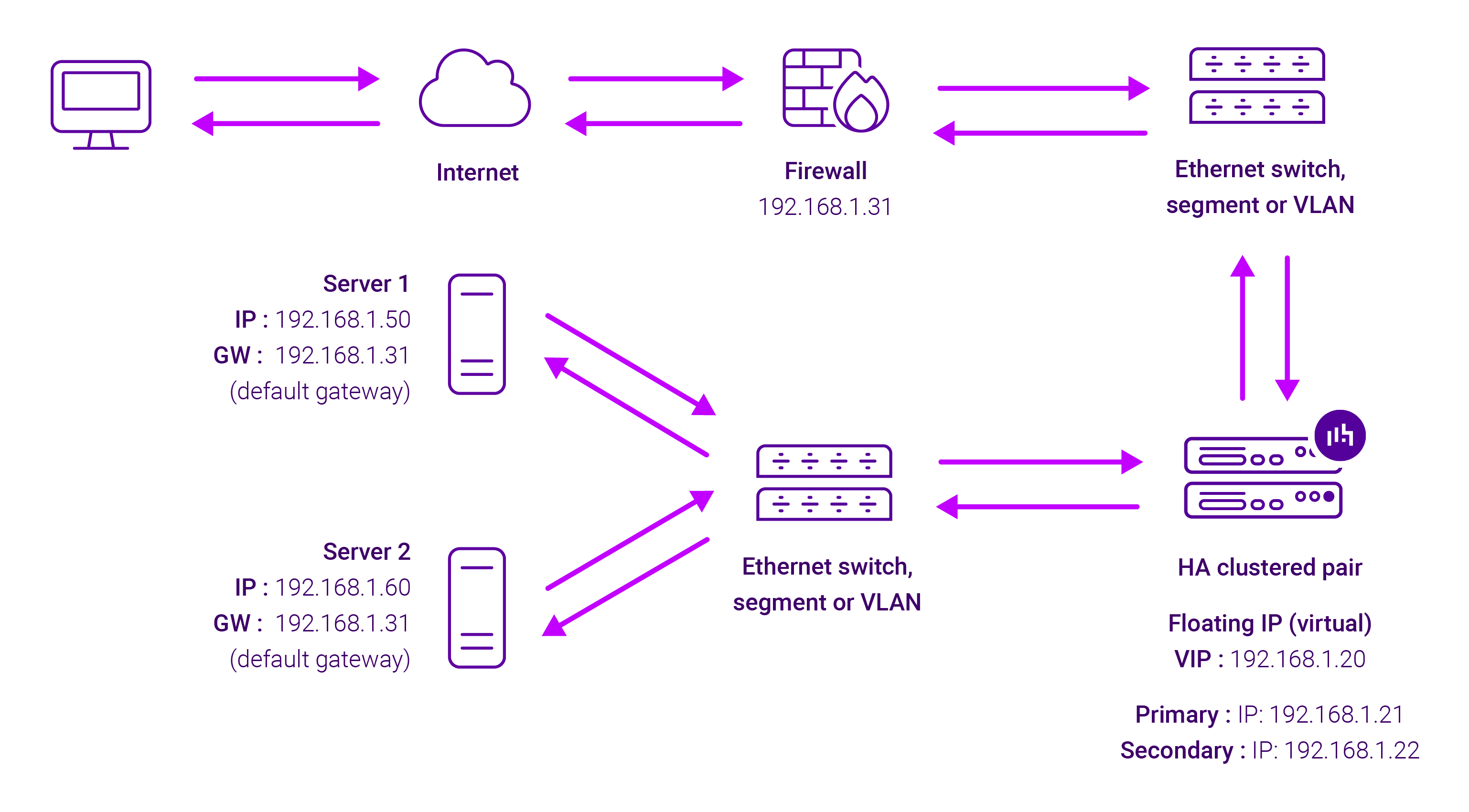
Because Layer 7 Reverse Proxy is a full proxy, Real Servers in the cluster can be on any accessible network including across the Internet or WAN.
Layer 7 Reverse Proxy is not transparent by default, i.e. the Real Servers will not see the source IP address of the client, they will see the load balancer’s own IP address by default, or any other local appliance IP address if preferred (e.g. the VIP address).
This can be configured per Layer 7 VIP. If required, the load balancer can be configured to provide the actual client IP address to the Real Servers in 2 ways. Either by inserting a header that contains the client’s source IP address, or by modifying the Source Address field of the IP packets and replacing the IP address of the load balancer with the IP address of the client. For more information on these methods, please refer to Transparency at Layer 7 in the Enterprise Admin Manual.