









Modern enterprise data centers have undergone a massive shift, moving away from rigid, hardware-bound silos into highly programmable, policy-driven fabrics. At the absolute forefront of this shift is Cisco Application Centric Infrastructure (ACI). By decoupling the control plane from the data forwarding plane, ACI makes managing and deploying network infrastructure an absolute dream.
However, as we scale these environments across geographically dispersed locations, a major challenge emerges: how do we gracefully handle traffic steering and High Availability?
That’s where Global Server Load Balancing (GSLB) comes into play. Integrating GSLB into Cisco ACI requires a nuanced understanding of both your network fabric and the load balancers handling your traffic. Let’s dive into how Cisco ACI topologies interact with GSLB, look at the operational hurdles of legacy approaches, and explore how we at Loadbalancer.org prefer to keep things simple.
Table of contents
- Foundational architecture: Pods, multi-pod, and multi-site
- Defining the target: What is GSLB actually balancing?
- The legacy hurdle: F5 BIG-IP iQuery and certificate complexity
- The Loadbalancer.org alternative: Smart GSLB
- Performance optimization through the Feedback Agent
- Troubleshooting Cisco ACI operational quirks
- Strategic approaches to multi-site resilience
Foundational architecture: Pods, multi-pod, and multi-site
To understand how to load balance a Cisco ACI fabric, we first have to look at its core building blocks: pods, multi-pod setups, and multi-site architectures.
- The pod: This is the baseline physical unit of the ACI fabric—a modular leaf-and-spine topology managed by a single Cisco Application Policy Infrastructure Controller (APIC) cluster. Within this single management domain, all of your infrastructure building blocks (tenants, VRFs, bridge domains, and EPGs) are shared natively across all nodes. A ‘pod’ acts as its own isolated failure domain with local routing protocols to ensure localized network issues don't cascade.
- Multi-pod: To get around the heavy scalability limitations and poor fault isolation of old-school stretched fabric designs, Cisco introduced multi-pod. This topology interconnects multiple separate leaf-and-spine groups (up to 12 pods) via a routed Inter-Pod Network (IPN). Crucially, the entire setup shares a single management brain (one central APIC cluster).
- Multi-site: When business-critical applications require an absolute air-gap safety net, multi-site is the architecture of choice. Multi-site connects completely distinct ACI fabrics, each running its own independent APIC cluster. This ensures that a messy configuration error or a catastrophic outage at Site A cannot physically impact Site B.
To see how multi-pod achieves failure isolation while remaining a single logical entity, let's look at the underlying protocol mechanisms:
| Protocol | Scope and function within a pod | Cross-pod mechanism (via IPN) |
|---|---|---|
| IS-IS | Manages Infrastructure Tunnel Endpoint (TEP) reachability. A failure in one pod leaves others unaffected. | Spines learn the TEP ranges of neighboring pods via OSPF over the IPN, then advertise them locally via IS-IS. |
| COOP | Manages local endpoint information and provides local failure isolation. | Endpoint entries are synced across the IPN between spines using MP-BGP EVPN. |
| MP-BGP EVPN | Not utilized for intra-pod reachability. | Acts as the core control plane for advertising endpoints between different pods. |
| VXLAN | Handles data plane encapsulation locally inside the pod. | All inter-pod traffic is encapsulated in VXLAN packets before being sent across the IPN. |
🛠️ Engineering decision point: Topology mapping
Are you deploying multi-pod or multi-site?
- Choose multi-pod if your primary goal is operational simplicity, active-active data center clustering, and seamless, live virtual machine mobility across Layer 3 domains under a single management pane.
- Choose multi-site if your security or compliance guidelines mandate a hard administrative air-gap where configuration blunders or control-plane meltdowns must be physically contained to a single geographic site.
Defining the target: What is GSLB actually balancing?
When we look at integrating GSLB into Cisco ACI, the primary objective is managing global application services. These services live behind Fully Qualified Domain Names (FQDNs)—like [www.example.com](https://www.example.com) —which must resolve to a specific IP address depending on where the user is located, the health of the application, and the current resource load.
Conceptually, the GSLB layer functions by load balancing the load balancers.
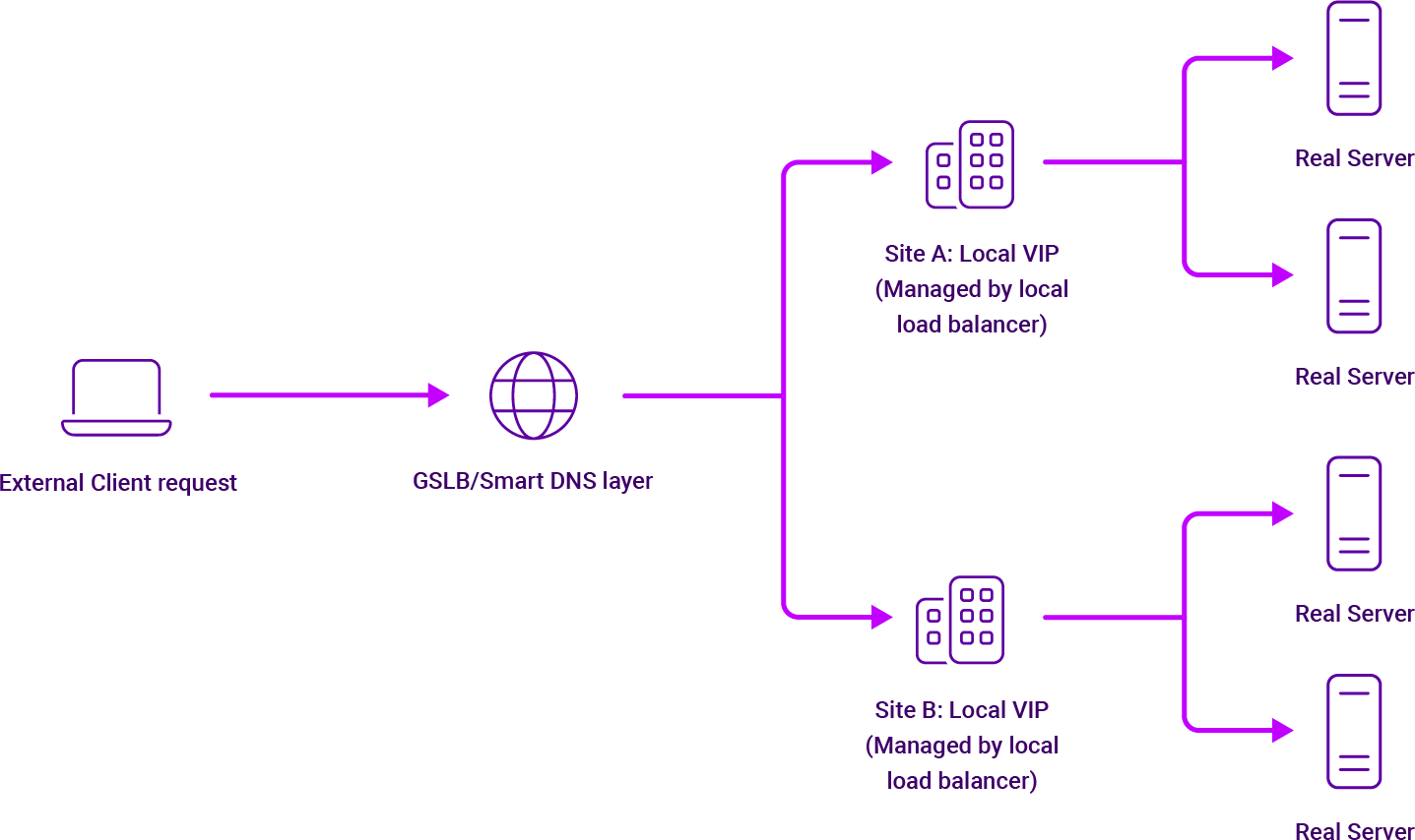
At each distinct site or pod, you configure a local Virtual Service with its own Virtual IP (VIP) on a local traffic manager. The GSLB layer intercepts the incoming DNS query and resolves the global FQDN to one of these local VIPs based on your business logic.
This tiered design gives you granular control over traffic steering while shielding your backend Real Servers from direct exposure to the public internet. It also allows local ADCs to handle heavy-lifting features like session persistence and HTTP header manipulations close to the workload, whether those workloads are traditional web apps, legacy healthcare modalities, or highly distributed object storage clusters.
🛠️ Engineering decision point: VIP placement
How should you map your GSLB targets?
- Ensure that every local pod or site containing an application instance has a uniquely assignable, non-overlapping local VIP configured on its local ADC. Do not attempt to stretch a single VIP across an ACI multi-site boundary via Layer 2 extensions for GSLB applications; instead, let the GSLB layer handle the site routing at the DNS layer to maintain your failure domain boundaries.
The legacy hurdle: F5 BIG-IP iQuery and certificate complexity
In traditional environments, legacy systems like F5 BIG-IP DNS (formerly GTM) use a rigid, hierarchical process to resolve these queries. It maps an FQDN to a Wide IP, pushes it down to a Pool, and uses a Preferred-Alternate-Fallback methodology to pick a VIP. If everything fails, it drops back to a local BIND configuration.
To make these decisions, the F5 DNS system must constantly talk to local traffic managers across different pods or sites using a proprietary protocol called iQuery (operating over TCP port 4353). iQuery shares real-time metrics like CPU overhead and active connection rates to help steer traffic away from struggling nodes.
However, in my conversations with enterprise engineers, the operational toll of managing an iQuery mesh is a massive pain point—particularly regarding SSL certificate management.
For successful mutual authentication, these systems must exchange device certificates that require strict Extended Key Usage (EKU) attributes: clientAuth for the requesting DNS machine and serverAuth for the responding local traffic manager. Because public Certificate Authorities (CAs) are increasingly enforcing a hard separation between serverAuth and clientAuth roots, using public CA-signed certificates for iQuery has become incredibly error-prone and frustrating. As a result, network teams are often left managing cumbersome, 10-year self-signed certificates or standing up complex internal CAs strictly to keep the iQuery mesh from collapsing.
🛠️ Engineering decision point: Control Plane overhead
How will you manage health-check telemetry?
- If you proceed with a legacy F5 iQuery setup, you must establish an automated certificate renewal and distribution strategy for port 4353. You'll need to explicitly design an internal PKI structure that allows dual-purpose (client and server authentication) EKU extensions to avoid silent sync failures across your ACI pods when certificates expire.
The Loadbalancer.org alternative: Smart GSLB
We believe that High Availability doesn't have to come with an enterprise tax or an army of specialists. Our Loadbalancer Enterprise appliance integrates robust GSLB as a core feature built on highly reliable, open source building blocks like PowerDNS and Polaris GSLB.
Let's look at how the two philosophies compare:
| Operational metric | Loadbalancer.org GSLB | F5 BIG-IP DNS |
|---|---|---|
| Licensing model | All-inclusive: GSLB is a core feature included at no extra cost in Enterprise models. | Expensive, separate add-on module or tiered licensing. |
| Deployment & setup | Sub-hour configuration: Managed via a clean, intuitive WebUI. | Days to weeks; typically requires specialized certification or professional services. |
| Control communication | Lightweight: Uses a streamlined Feedback Agent over port 3333. | Complex proprietary iQuery mesh over port 4353 with strict EKU certificate demands. |
| Throughput scaling | Horizontal scaling capabilities up to 2.8Tbps. | Hard-tied to rigid, modular hardware licensing tiers. |
| Lifecycle policy | No forced software End-of-Life: You control your upgrade cycles. | Standard EOL cycles that mandate costly refreshes. |
Our approach to Smart GSLB centers on application-aware locality rather than just basic geographic proximity. Standard Geo-IP setups simply look at a user’s physical distance from a data center and route them accordingly. Smart GSLB, however, pairs this distance with deep infrastructure data, mapping your internal subnet topologies. This ensures that local traffic stays local—a vital requirement for high-bandwidth applications where unnecessary cross-site WAN egress can lead to massive latency penalties and cloud egress bills.
🛠️ Engineering decision point: Local vs. wide routing
Is your traffic routing dictated by proximity or application state?
- When setting up your global routing topology, evaluate whether your WAN links can handle cross-site overflow. If they can't, implement a topology-weighted routing strategy within the GSLB tool to anchor users to their closest ACI pod, using remote sites strictly as a catastrophic fallback rather than an active-active buffer.
Performance optimization through the Feedback Agent
To move beyond blunt "is the port open?" health checks, we utilize a dynamic Feedback Agent. This lightweight agent installs directly onto your Windows or Linux application servers and feeds real-time telemetry straight back to the load balancer over port 3333.
Instead of guessing server health, the Feedback Agent reports exactly how much headroom the server has left by checking actual CPU and RAM utilization. The agent calculates a percentage idle value, allowing the GSLB to dynamically tweak server weights on the fly.
This entirely eliminates the notorious hot node problem, where a DNS server blindly sends a massive wave of new users to a nearby server that is already completely overwhelmed by active sessions. In a Cisco ACI environment—where two pods might sit right next to each other in a metro area but have wildly different compute capacities—this real-time awareness is a lifesaver.
Administrators can easily tune the agent's utilization calculations to prioritize the exact resource metrics that matter most to their specific applications:
Load calculation = (CPU × importance factor) + (RAM × importance factor)
By setting these custom importance factors and configuring guardrails (like a hard 85% RAM utilization limit), the load balancer can proactively steer new incoming requests away from a struggling node before it actually crashes.
🛠️ Engineering decision point: Telemetry strategy
Should you use standard Layer 4/7 health probes or dynamic agents?
- Use standard HTTP/HTTPS status probes for simple, lightweight web applications where state isn't heavily tied to system memory.
- Deploy the Feedback Agent if you are balancing intensive workloads (such as medical imaging systems or massive database front-ends) where a node can be logically ‘alive’ on port 443 but completely frozen due to CPU or memory starvation.
Troubleshooting Cisco ACI operational quirks
Deploying any load balancer within a Cisco ACI fabric requires navigating a few unique architectural quirks. Because ACI completely decouples the control plane from the physical hardware, things can get tricky during an appliance failover or when deploying in Direct Routing mode.
Taming IP data-plane learning
By default, the Cisco ACI switching fabric learns source IP addresses dynamically from all active data-plane traffic, not just from standard ARP messages. This means the network fabric remembers where an IP lives based on any active network flow.
During an HA failover event, when a secondary load balancer steps up to take over a VIP, it broadcasts a Gratuitous ARP (GARP) to tell the network it has moved. However, if the ACI fabric continues to listen to stale data-plane traffic floating around from old connections, the VIP won't migrate to the new active node properly, resulting in a black hole for your traffic.
To ensure seamless failover, we recommend three non-negotiable configuration steps within your ACI environment:
- L4-L7 VIP definition: Explicitly define your VIP inside the ACI APIC under your specific Endpoint Group (EPG) settings. This alerts the fabric that this specific IP is a shared service address.
- Enable GARP-based detection: Inside your Bridge Domain configuration, turn on GARP-based detection. This tells the ACI fabric to prioritize incoming ARP messages above all else when tracking the physical location of that IP.
- Fabric verification: Always verify that the fabric has logged the IP correctly by hopping onto the ACI leaf CLI and running: show system internal epm endpoint ip <VIP_IP> Look for the internal VIP flag to confirm it’s configured properly.
Direct Routing (DSR) and the ARP problem
In ultra-high-performance environments, Direct Server Return (DSR)—also known as Direct Routing (DR)—is the gold standard. In a DSR setup, the load balancer only handles the incoming request. The backend server bypasses the load balancer entirely on the way out, responding directly to the client over the network. For throughput-heavy workloads like streaming media or object storage, this is roughly 8 to 50 times faster than traditional NAT-based methods.
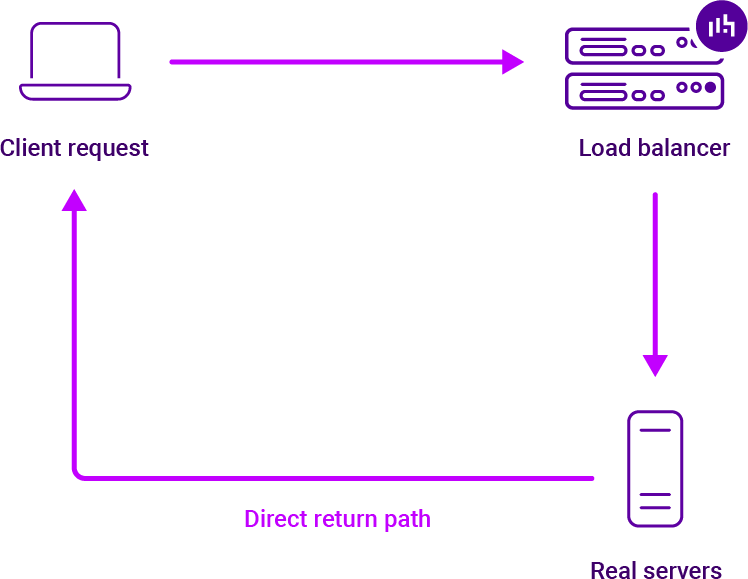
However, DSR requires solving the classic ARP problem. The real backend servers must be configured to accept traffic addressed to the VIP, but they must never respond to network-wide ARP requests for that VIP. If they do, they will steal traffic directly from the load balancer.
On Windows nodes, you solve this by installing a Microsoft Loopback Adapter, binding the VIP to it, and setting up a weak/strong host routing model. If you don't meticulously manage these host-level settings within a Cisco ACI environment, the switching fabric will accidentally learn the MAC address of one of your backend servers for that VIP, causing your entire application traffic flow to collapse into a single server node.
🛠️ Engineering decision point: Failover & routing modes
Which network topology fits your performance requirements?
- Choose standard SNAT/NAT mode if you want simple, out-of-the-box configuration without touching the network stack of your backend servers.
- Choose Direct Routing (DSR) if you are pushing massive amounts of data and require extreme throughput. If you choose DSR, you must configure the ACI Bridge Domain with "GARP-based detection" and verify that all loopback adapters on your backend hosts are completely silent to avoid MAC flapping on your ACI leaf switches.
Strategic approaches to multi-site resilience
When building out your global architecture across ACI Multi-Pod or Multi-Site frameworks, you have several advanced traffic distribution methods at your disposal:
- Failover Group (fogroup): Chains your site members in a strict order of preference. This is perfect for classic Active-Passive Disaster Recovery configurations.
- Weighted Round Robin (wrr): Spreads incoming queries across your data centers based on predefined ratios, allowing for smooth Active-Active capacity balancing.
- Topology Weighted (twrr): Checks the source IP subnet of the DNS requester and pairs them with the closest resource, minimizing cross-site WAN latency and egress fees.
- Smart DNS (SDNS): Routes users directly to individual storage or application nodes, bypassing local ADCs entirely after the initial DNS resolution.
The Direct-to-Node (SDNS) superpower
For massive enterprise object storage deployments like NetApp StorageGRID or Splunk SmartStore, our Smart DNS (SDNS) approach is incredibly powerful. By pulling the load balancer completely out of the active data path after the initial DNS handshake, your system throughput is limited only by your raw network hardware. Paired with our Feedback Agent on each storage node, GSLB ensures new connections are always pointed to the quietest storage node in the cluster, keeping utilization perfectly balanced.
Beating the DNS caching nightmare
The biggest headache in GSLB deployment is that client devices and intermediate recursive resolvers love to aggressively cache DNS records, completely ignoring your carefully planned failover configurations. If a site suffers a sudden outage, cached records can leave users stranded on a dead IP.
We solve this by supporting a Time-to-Live (TTL) of zero alongside the Extension Mechanism for DNS (EDNS). EDNS passes the actual client's real IP subnet up to the GSLB layer, allowing for highly accurate routing. Combining this with a zero TTL ensures that DNS answers are always fresh, drastically minimizing the downtime window during an unexpected multi-site failover.
You still have a small risk that legacy clients will ignore the TTL setting, but in my experience that is very unusual.
Security, compliance, and data sovereignty
GSLB isn't just about speed and uptime—it's also a powerful tool for regulatory compliance. If your organization operates across strict legal borders (like GDPR in Europe or CCPA in California), you can use topology-based GSLB routing to build rigid compliance guardrails. This ensures that users from specific geographic zones are strictly routed to data centers operating within those legal boundaries, keeping your data handling entirely compliant.
🛠️ Engineering decision point: Traffic steering selection
What's your primary multi-site KPI?
- For active-passive compliance or DR: Map your sites using a Failover Group (fogroup) combined with a near-zero TTL to enforce immediate failover.
- For high-throughput object storage: Deploy Smart DNS (SDNS) in conjunction with the Feedback Agent on your storage nodes to completely bypass the load balancer data plane bottleneck and maximize your network hardware investment.
Conclusion: A strategic blueprint for GSLB in Cisco ACI
Integrating an intelligent GSLB layer into a Cisco ACI multi-pod or multi-site environment shouldn't feel like an uphill battle against licensing costs and configuration clutter. By focusing on infrastructure locality, real-time server telemetry, and an intimate understanding of ACI’s data-plane learning quirks, you can build an incredibly resilient, high-performance application delivery fabric.
At Loadbalancer.org, our goal is to provide enterprise-grade resilience and massive throughput scaling without the bloated legacy pricing or forced hardware refresh cycles. It's a clean, reliable strategy designed to help your network teams deploy quickly, scale seamlessly, and keep traffic flowing exactly where it needs to go.
Make multi-site easier with smart GSLB.

Building resilient neocloud S3 storage architecture: The critical role of load balancing


Related posts
Multi-site HPE Alletra Storage MP X10000 with Global Server Load Balancing

What's the best cloud load balancer? AWS, Azure, GCP, Cloudflare, or a third-party alternative?
Multi-AZ resilience: Why the recent AWS outage shows you need it
Help! Our legacy modalities are awesome — but they don't understand DNS!

High zero-day in Citrix NetScaler ADC & Gateway: Patch CVE-2026-88779

Critical zero-day in F5 BIG-IP APM: Emergency CVE-2026-94127 hotfixes released
Critical zero-days in Citrix NetScaler ADC & Gateway: Patch CVE-2026-88771 and CVE-2026-88772 immediately
The ultimate VMware NSX alternative: Nutanix + Loadbalancer.org