Load balancing TeraRecon Aquarius iNtuition
Updated on May 12, 2026
•
Published on May 11, 2026
Benefits of load balancing TeraRecon Aquarius iNtuition
The three main benefits of load balancing TeraRecon Aquarius iNtuition are:
- High Availability: In a clinical environment, radiologists and surgeons need 24/7 access to 3D reconstructions. By load balancing multiple iNtuition rendering nodes, you eliminate a single point of failure while the load balancer also performs health checks on each server. If one server goes down for maintenance or crashes, the load balancer automatically reroutes traffic to the remaining healthy nodes. This ensures that the clinical team are never impacted by downtime during critical procedures.
- Optimized performance and speed: Advanced visualization is resource-intensive, requiring significant GPU and CPU power to render thin client views. Without load balancing, one server might be overwhelmed by five simultaneous users performing complex cardiac analyses while another server sits idle. Thankfully, the load balancer is able to distribute incoming sessions based on the Least Connections or resource usage of each server. This ensures that every user gets a responsive, lag-free experience, which is vital for time-sensitive tasks like stroke or trauma assessments.
- Seamless scalability: As a hospital’s imaging volume grows—for example, adding a new 320-slice CT scanner—the demand on iNtuition increases. Load balancing allows you to add new rendering servers to the pool without any reconfiguration on the user’s end. You can also scale out the infrastructure during work hours by simply plugging in a new node and adding it to the load balancer’s rotation. The system instantly begins using the new capacity to handle more concurrent users across the enterprise.
About TeraRecon Aquarius iNtuition
TeraRecon Aquarius iNtuition is a premier, server-based advanced medical imaging and visualization software used by clinicians to analyze 2D, 3D, and 4D images from CT, MR, and other modalities.
It enables real-time volumetric analysis, vessel analysis, and pre-operative planning, featuring zero-click automation for tasks like cardiac imaging and EVAR planning.
Why Loadbalancer.org for TeraRecon Aquarius iNtuition?
Loadbalancer’s intuitive Enterprise Application Delivery Controller (ADC) is designed to save time and money with a clever, not complex, WebUI.
Easily configure, deploy, manage, and maintain our Enterprise load balancer, reducing complexity and the risk of human error. For a difference you can see in just minutes.
And with WAF and GSLB included straight out-of-the-box, there’s no hidden costs, so the prices you see on our website are fully transparent.
More on what’s possible with Loadbalancer.org.
How to load balance TeraRecon Aquarius iNtuition
The load balancer can be deployed in 4 fundamental ways: Layer 4 DR mode, Layer 4 NAT mode, Layer 4 SNAT mode, and Layer 7 Reverse Proxy (Layer 7 SNAT mode).
For TeraRecon Aquarius iNtuition, Layer 7 Reverse Proxy mode is recommended.
Virtual service (VIP) requirements
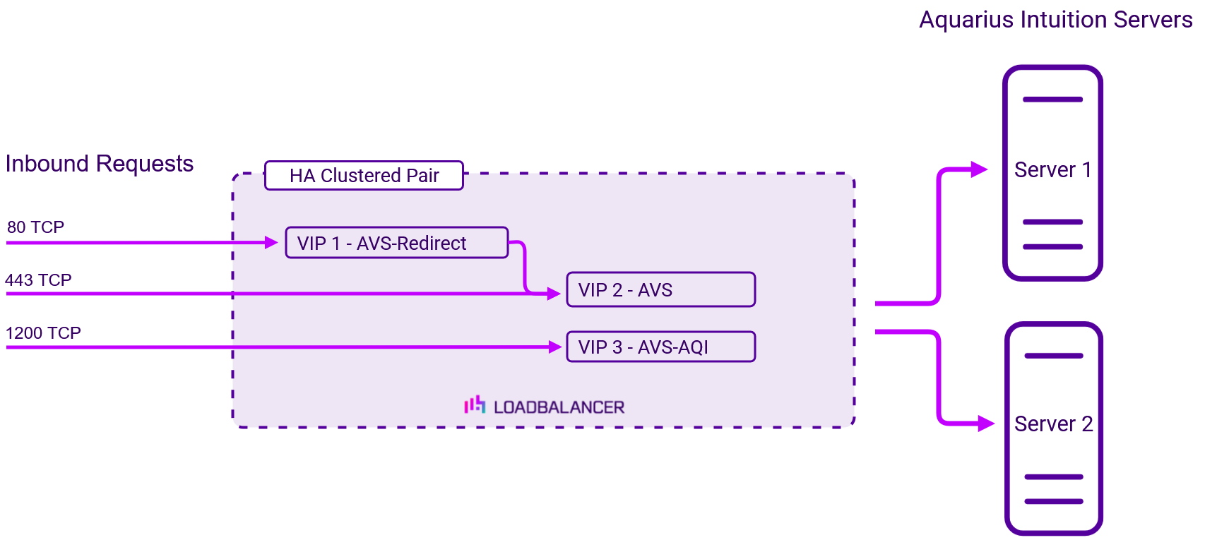
To provide load balancing and HA for TeraRecon Aquarius iNtuition, the following VIPs are required:
| Ref | VIP Name | Mode | Port(s) | Persistence Mode | Health Check |
|---|---|---|---|---|---|
| VIP 1 | AVS-Redirect | Layer 7 Reverse Proxy (HTTP) | 80 | – | – |
| VIP 2 | AVS | Layer 7 Reverse Proxy (HTTP/2) | 443 | HTTP Cookie | Connect to Port |
| VIP 3 | AVS-AQI | Layer 7 Reverse Proxy (TCP) | 1200 | Source IP | Connect to Port |
Load balancing deployment concept
Once the load balancer is deployed, clients connect to the Virtual Services (VIPs) rather than connecting directly to one of the TeraRecon Aquarius iNtuition servers. These connections are then load balanced across the TeraRecon Aquarius iNtuition servers to distribute the load according to the load balancing algorithm selected.
About Layer 7 Reverse Proxy load balancing
Layer 7 Reverse Proxy uses a proxy (HAProxy) at the application layer. Inbound requests are terminated on the load balancer and HAProxy generates a new corresponding request to the chosen Real Server. As a result, Layer 7 is typically not as fast as the Layer 4 methods. Layer 7 is typically chosen when either enhanced options such as SSL termination, cookie based persistence, URL rewriting, header insertion/deletion etc. are required, or when the network topology prohibits the use of the Layer 4 methods. The image below shows an example network diagram for this mode.
The image below shows an example Layer 7 Reverse Proxy network diagram:

Because Layer 7 Reverse Proxy is a full proxy, Real Servers in the cluster can be on any accessible network including across the Internet or WAN.
Layer 7 Reverse Proxy is not transparent by default, i.e. the Real Servers will not see the source IP address of the client, they will see the load balancer’s own IP address by default, or any other local appliance IP address if preferred (e.g. the VIP address).
This can be configured per Layer 7 VIP. If required, the load balancer can be configured to provide the actual client IP address to the Real Servers in 2 ways. Either by inserting a header that contains the client’s source IP address, or by modifying the Source Address field of the IP packets and replacing the IP address of the load balancer with the IP address of the client. For more information on these methods, please refer to Transparency at Layer 7 in the Enterprise Admin Manual.