Load balancing Panzura Cloud File System
Updated on October 23, 2025
•
Published on March 7, 2023
Benefits of load balancing Panzura Cloud File System
Load balancing Panzura Cloud File System offers a number of benefits, including:
- High Availability (HA): Load balancing distributes inbound connections across a cluster of Panzura CloudFS nodes. This architecture ensures that if one node fails or goes down, traffic is automatically redirected to the other healthy nodes. This removes the single point of failure, preventing downtime and maintaining continuous service availability for users, which is crucial for business continuity.
- Improved performance and scalability: By distributing client requests and workloads evenly, load balancing ensures that no single CloudFS node becomes overwhelmed. This leads to optimized resource usage with workloads spread out, utilizing the capacity of all available nodes efficiently. As data demands and user traffic grow, new CloudFS nodes can also be added behind the load balancer, allowing the system to scale its performance capacity without disruption to the end user.
- Consistent user experience: Load balancing can be deployed to manage traffic across geographically dispersed nodes, which is particularly relevant for Panzura’s global file system. This helps ensure users are typically directed to the closest or most responsive node, providing a local-feeling file performance regardless of their geographic location. Combined with CloudFS’s global file locking and immediate data consistency, load balancing means that all users, across all locations, have fast, reliable access to the same single, authoritative data set.
About Panzura Cloud File System
The Panzura Cloud File System (PCFS) is a distributed cloud file system used for storing application data that spans the globe, granting users in various geographical locations fast and consistent access to that data. It’s a “NAS in the sky”.
Why Loadbalancer.org for Panzura Cloud File System?
Loadbalancer’s intuitive Enterprise Application Delivery Controller (ADC) is designed to save time and money with a clever, not complex, WebUI.
Easily configure, deploy, manage, and maintain our Enterprise load balancer, reducing complexity and the risk of human error. For a difference you can see in just minutes.
And with WAF and GSLB included straight out-of-the-box, there’s no hidden costs, so the prices you see on our website are fully transparent.
More on what’s possible with Loadbalancer.org.
How to load balance Panzura Cloud File System
The load balancer can be deployed in 4 fundamental ways: Layer 4 DR mode, Layer 4 NAT mode, Layer 4 SNAT mode, and Layer 7 Reverse Proxy (Layer 7 SNAT mode).
For Panzura CloudFS, using either Layer 4 NAT mode or Layer 7 Reverse Proxy is recommended. Where possible, we recommend that Layer 7 SNAT mode is used. This mode offers great performance with minimal to no changes required on the real servers and can be deployed in one-arm or two-arm mode. HAProxy is a high performance solution, but since it operates as a full proxy, it cannot perform as fast as the Layer 4 solutions. Layer 7 Reverse Proxy is non-transparent by default, i.e. the Real Servers will see the source IP address of the load balancer.
Layer 4 DR mode is not recommended due to operating system restrictions on the Panzura CloudFS nodes. These modes are described below and are used for the configurations presented in this guide.
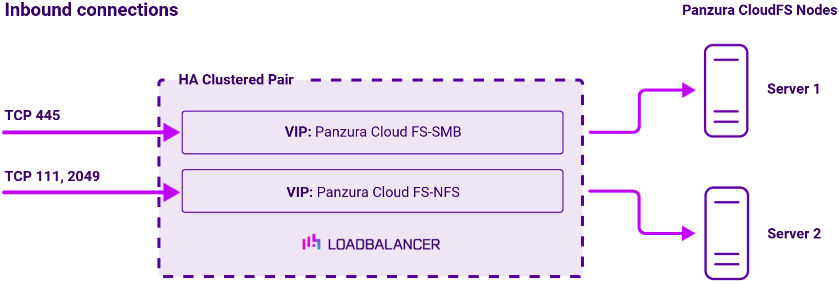
Virtual service (VIP) requirements
To provide load balancing for Panzura CloudFS, the following VIPs are required:
- SMB: for Windows print and file sharing cluster
- NFS: Network file system cluster
Port requirements
The following table shows the ports that are load balanced:
| Port | Protocol | Uses |
|---|---|---|
| 111 | TCP/RPC | Remote Procedure Call / portmap traffic (RPC) |
| 445 | TCP/SMB | Windows File and print sharing |
| 2049 | TCP/NFS | NFS daemon process (nfsd) |
Load balancing deployment concept
Note
The load balancer can be deployed as a single unit, although Loadbalancer.org recommends a clustered pair for resilience and high availability.
About Layer 4 NAT mode load balancing
This mode is a high performance solution, although not as fast as DR mode. It requires the implementation of a two-arm infrastructure with an internal and external subnet to carry out the translation (the same way a firewall works). Also, each Real Server must use the load balancer as the default gateway. Layer 4 NAT mode is transparent, i.e. the Real Servers will see the source IP address of the client.
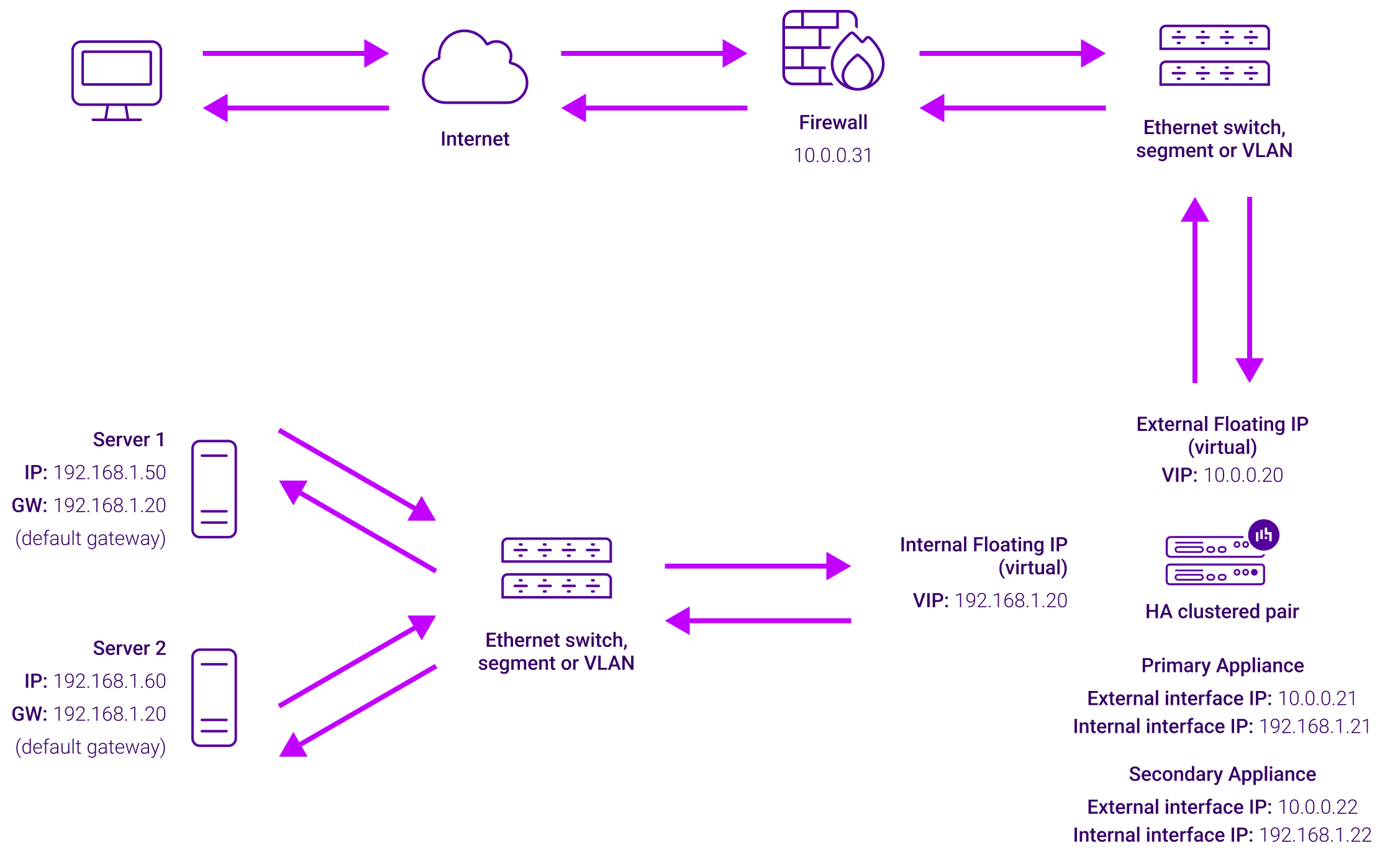
Load balancing topology
The load balancer translates all requests from the external Virtual Service to the internal Real Servers. Normally eth0 is used for the internal network and eth1 is used for the external network although this is not mandatory. If the Real Servers require Internet access, Autonat should be enabled using the WebUI option: Cluster Configuration > Layer 4 – Advanced Configuration, the external interface should be selected.
NAT mode can be deployed in the following ways:
- 2-arm (using 2 Interfaces), 2 subnets (as shown above) – One interface on the load balancer is connected to subnet1 and the second interface and Real Servers are connected to subnet2. The VIP is brought up in subnet1. The default gateway on the Real Servers is set to be an IP address in subnet2 on the load balancer. Clients can be located in subnet1 or any remote subnet provided they can route to the VIP.
- 2-arm (using 1 Interface), 2 subnets – same as above except that a single interface on the load balancer is allocated 2 IP addresses, one in each subnet.
- 1-arm (using 1 Interface), 1 subnet – Here, the VIP is brought up in the same subnet as the Real Servers. For clients located in remote networks the default gateway on the Real Servers must be set to be an IP address on the load balancer. For clients located on the same subnet, return traffic would normally be sent directly to the client bypassing the load balancer which would break NAT mode. To address this, the routing table on the Real Servers must be modified to force return traffic to go via the load balancer – For more details on ‘One-Arm NAT Mode’ refer to the administration manual.
If you want Real Servers to be accessible on their own IP address for non-load balanced services, e.g. SMTP or RDP, you will need to setup individual SNAT and DNAT firewall script rules for each Real Server or add additional VIPs for this – please refer to the administration manual for more details.
NAT mode is transparent, i.e. the Real Server will see the source IP address of the client. Port translation is possible in NAT mode, i.e. VIP:80 –> RIP:8080 is possible.
About Layer 7 Reverse Proxy load balancing
Layer 7 Reverse Proxy uses a proxy (HAProxy) at the application layer. Inbound requests are terminated on the load balancer and HAProxy generates a new corresponding request to the chosen Real Server. As a result, Layer 7 is typically not as fast as the Layer 4 methods. Layer 7 is typically chosen when either enhanced options such as SSL termination, cookie based persistence, URL rewriting, header insertion/deletion etc. are required, or when the network topology prohibits the use of the Layer 4 methods.
The image below shows an example Layer 7 Reverse Proxy network diagram: