Load balancing iTernity iCAS File Storage
Updated on March 23, 2026
•
Published on March 23, 2026
Benefits of load balancing iCAS FS
Load balancing an iTernity iCAS FS (File Storage) cluster is essential because it is a scale-out architecture. While iCAS FS has built-in High Availability, a third-party load balancer optimizes how data flows through the system.
Here are the top 3 benefits of load balancing iCAS FS:
- High Availability and automatic failover: iCAS FS is designed to be a self-healing cluster. If a single storage node fails or goes offline for maintenance, a load balancer ensures the system remains accessible by transparently re-routing traffic to the remaining healthy nodes. This means business applications (such as ERP, PACS, and email) never lose connection to the archive, preventing ‘server not found’ errors and ensuring 24/7 data access.
- Optimized performance and throughput: In a scale-out system, hotspots (where one server is doing all the work while others sit idle) should be avoided. A load balancer uses algorithms like Least Connections to distribute incoming read/write requests across all nodes in the cluster. This maximizes the hardware’s potential, reducing latency for end users and increasing the overall speed of data ingestion (backup/archiving) and retrieval.
- Simplified scalability: One of the main selling points of iCAS FS is the ability to ‘start small and grow’. When a new storage node is added to increase capacity, a load balancer allows that node to be integrated into the existing environment without changing the configuration of the connected applications. This means the storage pool can be expanded on the fly. The load balancer simply starts sending a share of the traffic to the new node as soon as it’s healthy, making growth seamless and non-disruptive.
About iCAS FS
iTernity iCAS (iTernity Compliant Archive Software) is a software-defined archiving solution designed to protect the integrity and long-term availability of business-critical data.
It essentially acts as a security layer or middleware between business applications (like ERP, CRM, or email systems) and physical storage hardware. Its primary goal is to ensure that archived data remains immutable, tamper-proof, and compliant with global regulations.
Why Loadbalancer.org for iTernity iCAS FS?
Loadbalancer’s intuitive Enterprise Application Delivery Controller (ADC) is designed to save time and money with a clever, not complex, WebUI.
Easily configure, deploy, manage, and maintain our Enterprise load balancer, reducing complexity and the risk of human error. For a difference you can see in just minutes.
And with WAF and GSLB included straight out-of-the-box, there’s no hidden costs, so the prices you see on our website are fully transparent.
For full benefits of this iTernity/Loadbalancer.org integration, check out this solution overview:
How to load balance iCAS FS
The load balancer can be deployed in 4 fundamental ways: Layer 4 DR mode, Layer 4 NAT mode, Layer 4 SNAT mode, and Layer 7 Reverse Proxy (Layer 7 SNAT mode).
For iCAS FS, Layer 7 Reverse Proxy is recommended.
Virtual service (VIP) requirements
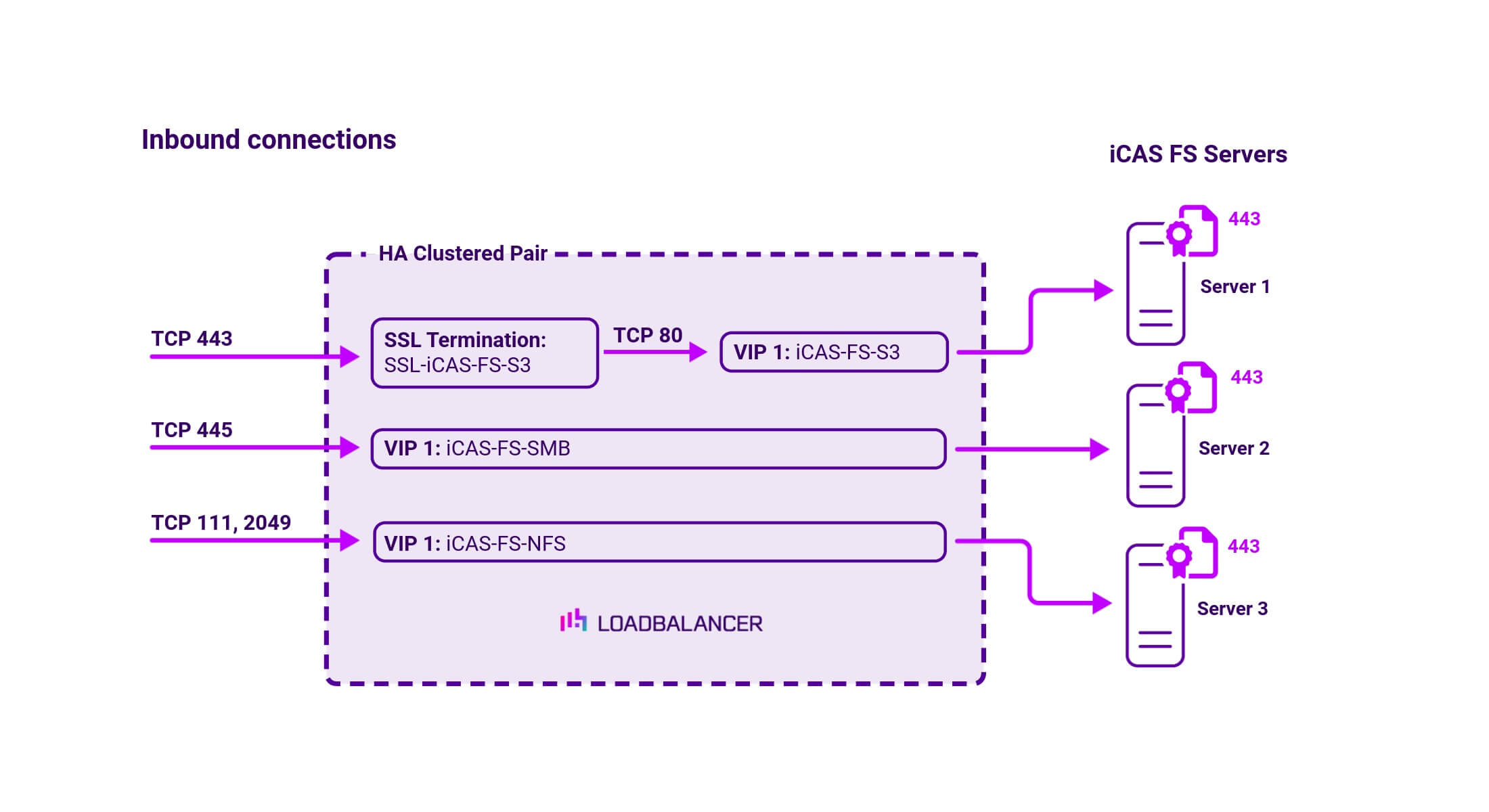
To provide load balancing and HA for iCAS FS, the following VIPs are required:
| Ref. | VIP Name | Mode | Port(s) | Persistence Mode | Health Check |
|---|---|---|---|---|---|
| VIP 1 | iCAS-FS-S3 | L7 Reverse Proxy (HTTP) | 80 | None | HTTP (GET) |
| VIP 2 | iCAS-FS-SMB | L7 Reverse Proxy (TCP) | 445 | None | Connect to Port |
| VIP 3 | iCAS-FS-NFS | L7 Reverse Proxy (TCP) | 111, 2049 | None | Connect to Port |
Load balancing deployment concept
About Layer 7 Reverse Proxy load balancing
Layer 7 Reverse Proxy uses a proxy (HAProxy) at the application layer. Inbound requests are terminated on the load balancer and HAProxy generates a new corresponding request to the chosen Real Server. As a result, Layer 7 is typically not as fast as the Layer 4 methods.
Layer 7 is typically chosen when enhanced options such as SSL termination, cookie based persistence, URL rewriting, header insertion/deletion etc. are required, or when the network topology prohibits the use of the Layer 4 methods.

Because Layer 7 Reverse Proxy is a full proxy, any server in the cluster can be on any accessible subnet, including across the Internet or WAN.
Layer 7 Reverse Proxy is not transparent by default i.e. the Real Servers will not see the source IP address of the client, they will see the load balancer’s own IP address by default, or any other local appliance IP address if preferred (e.g. the VIP address). This can be configured per Layer 7 VIP.
If required, the load balancer can be configured to provide the actual client IP address to the Real Servers in two ways:
- Either by inserting a header that contains the client’s source IP address, or
- By modifying the Source Address field of the IP packets and replacing the IP address of the load balancer with the IP address of the client.
Layer 7 Reverse Proxy mode can be deployed using either a one-arm or two-arm configuration. For two-arm deployments, eth0 is normally used for the internal network and eth1 is used for the external network, although this is not mandatory.
No mode-specific configuration changes to the load balanced Real Servers are required.
Port translation is possible with Layer 7 Reverse Proxy e.g. VIP:80 → RIP:8080 is supported. You should not use the same RIP:PORT combination for Layer 7 Reverse Proxy VIPs and Layer 4 SNAT mode VIPs because the required firewall rules conflict.