Load balancing GE HealthCare Centricity PACS
Updated on February 3, 2026
•
Published on July 23, 2024
Benefits of load balancing GE HealthCare Centricity PACS
Load balancing GE Healthcare Centricity PACS provides a number of benefits that collectively contribute to enhanced workflow efficiency for radiologists and caregivers by ensuring timely and reliable access to imaging data:
- High Availability (HA): Load balancing ensures that the Centricity PACS system remains continuously available, which is vital in a healthcare setting where downtime can directly impact patient care and diagnosis. By distributing incoming traffic (like DICOM studies and retrieval requests) across multiple servers, the system avoids having a single point of failure. If one server experiences a failure or becomes unresponsive, the load balancer automatically and seamlessly redirects all traffic to the remaining healthy servers (a process called failover). This redundancy means physicians and radiologists maintain uninterrupted access to critical patient images and clinical records at all times, supporting timely diagnosis and treatment.
- Optimal performance: Load balancing distributes the workload to prevent any single PACS server from becoming overwhelmed, leading to faster service and the ability to grow the system easily. Requests are intelligently routed to the server with the least current load or best performance, which reduces latency and ensures rapid access to large medical images and records. This is especially important for high-volume environments or during peak hours (e.g., in the Emergency Department).
- Scalability for growth: As a healthcare organization grows—acquiring more imaging equipment, adding departments, or managing increasing patient volumes—load balancing allows the IT team to easily add new servers to the PACS cluster without disrupting existing services, accommodating the massive growth of medical imaging data.
About GE HealthCare Centricity PACS
The GE Centricity suite of products for Enterprise Imaging provides a common viewing, workflow and archiving medical imaging solution which integrates PACS, RIS, CVIT, VNA and cloud-based sharing solutions.
For caregivers to work effectively, peak performance of these applications is crucial. Doctors demand instant image and data retrieval, zero downtime, and systems which are easy to maintain with simple security updates.
Clustering multiple load balanced GE Centricity PACS servers provides product managers with a fast cost-effective, highly available and scalable solution, in an environment where study volume is ever increasing.
Why Loadbalancer.org for GE HealthCare Centricity PACS
This deployment guide isn’t theoretical; it has been field tested and rigorously validated by GE HealthCare experts. This means you can be completely confident that the solution described is robust, reliable, and backed by the real-world operational experience of a global leader in healthcare technology.
Loadbalancer’s intuitive Enterprise Application Delivery Controller (ADC) is designed to save time and money with a clever, not complex, WebUI.
Easily configure, deploy, manage, and maintain our Enterprise load balancer, reducing complexity and the risk of human error. For a difference you can see in just minutes.
And with WAF and GSLB included straight out-of-the-box, there’s no hidden costs, so the prices you see on our website are fully transparent.
More on what’s possible with Loadbalancer.org.
How to load balance GE HealthCare Centricity PACS
The load balancer can be deployed in four fundamental ways: Layer 4 DR mode, Layer 4 NAT mode, Layer 4 SNAT mode, and Layer 7 Reverse Proxy (Layer 7 SNAT mode).
For GE HealthCare Centricity PACS, both Layer 4 DR mode and Layer 7 Reverse Proxy mode are recommended.
Virtual service (VIP) requirements
To provide load balancing and HA for CPACS, the following VIPs are required:
| Ref. | VIP Name | Mode | Port(s) | Persistence Mode | Health Check |
|---|---|---|---|---|---|
| VIP 1 | EA_XDS_Service | Layer 4 DR | 80 | None | HTTP (GET) |
| VIP 2 | EA_Dicom_Service | Layer 4 DR | 104 | None | HTTP (GET) |
| VIP 3 | EA_Secure_Dicom_Service | Layer 4 DR | 2762 | None | HTTP (GET) |
| VIP 4 | EA_HL7_Service | Layer 4 DR | 2575 | None | HTTP (GET) |
| VIP 5 | EA_Secure_HL7_Service | Layer 4 DR | 2576 | None | HTTP (GET) |
| VIP 6 | EA_Study_Management_Service | Layer 4 DR | 443 | Source IP | HTTP (GET) |
| VIP 7 | DB_MT | Layer 4 SNAT | All ports except 20000 | Source IP | Connect to Port |
| VIP 8 | DB_DBVIP | Layer 4 SNAT | 20000 | None | ICMP Ping |
| VIP 9 | DAS_Pool | Layer 4 DR | 4100,8080,104 | Source IP | HTTP (GET) |
| VIP 10 | ZFP | Layer 7 Reverse Proxy | 443 | Source IP | HTTPS (GET) |
| VIP 11 | UV | Layer 7 Reverse Proxy | 443 | Source IP | HTTPS (GET) |
| VIP 12 | Dakota | Layer 7 Reverse Proxy | SP1: 8080, SP2: 8443 | Source IP | SP1: Connect to port, SP2: HTTPS (GET) |
| VIP 13 | WFM_Play_Group | Layer 7 Reverse Proxy | SP1: 8080, SP2: 9443 | Source IP | HTTPS (GET) |
| VIP 14 | WFM_tomcat_Group | Layer 7 Reverse Proxy | SP1: 9096, SP2: 9096,3443 | Source IP | HTTPS (GET) |
| VIP 15 | XE_Standalone | Layer 7 Reverse Proxy | 8443,9449 | Source IP | HTTPS (GET) |
| VIP 16 | CCG_IB_2101 | Layer 7 Reverse Proxy | 2101 | Last successful | Connect to Port |
| VIP 17 | CCG_IB_2102 | Layer 7 Reverse Proxy | 2102 | Last successful | Connect to Port |
| VIP 18 | PORT_CCG_IB_2103 | Layer 7 Reverse Proxy | 2103 | Last successful | Connect to Port |
| VIP 19 | PORT_CCG_IB_2104 | Layer 7 Reverse Proxy | 2104 | Last successful | Connect to Port |
Load balancing deployment concept
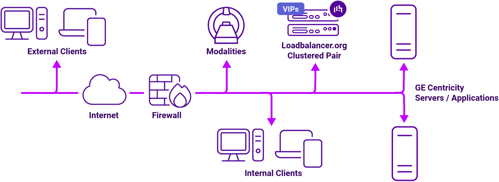
The load balancer can be deployed in 4 fundamental ways: Layer 4 DR mode, Layer 4 NAT mode, Layer 4 SNAT mode, and Layer 7 SNAT mode. For GE Centricity PACS, a combination of layer 4 SNAT mode and layer 7 SNAT mode is recommended.
By utilizing Layer 4 DR mode, our entry-level Enterprise Prime easily handles environments of up to 500k studies/year. For anything larger, our Enterprise Flex offers an infinitely scalable solution at an unbelievable price-point.
Having partnered with top-tier healthcare vendors, Loadbalancer.org brings expert consultancy and support to all of our deployments. Our extensive experience in Enterprise Imaging means that we understand the challenges you face, and are ready to meet them with tried-and-tested solutions.
About Layer 4 DR mode load balancing
One-arm direct routing (DR) mode is a very high performance solution that requires little change to your existing infrastructure.
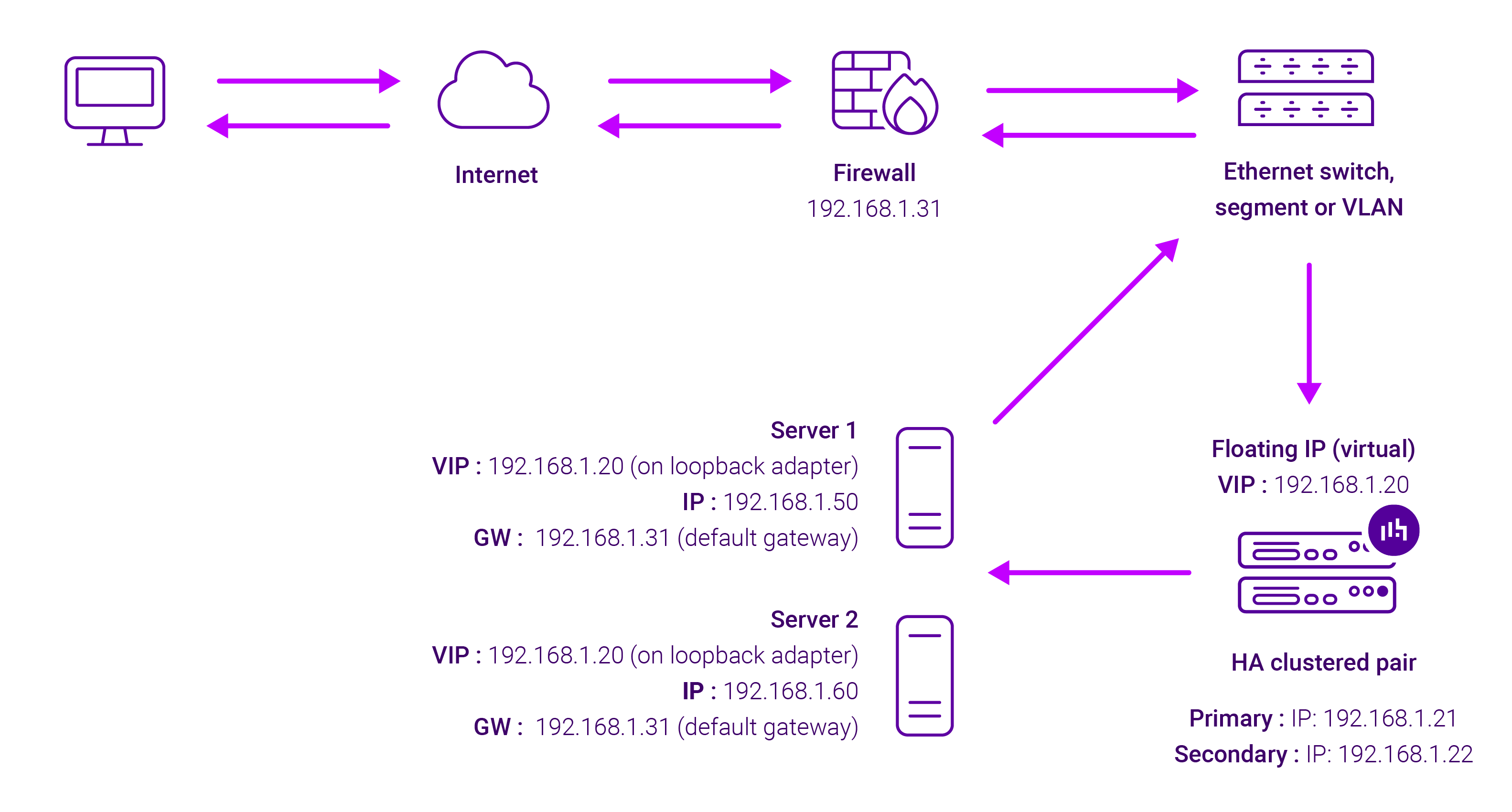
DR mode works by changing the destination MAC address of the incoming packet to match the selected Real Server on the fly which is very fast.
When the packet reaches the Real Server it expects the Real Server to own the Virtual Services IP address (VIP). This means that you need to ensure that the Real Server (and the load balanced application) respond to both the Real Server’s own IP address and the VIP.
The Real Servers should not respond to ARP requests for the VIP. Only the load balancer should do this. Configuring the Real Servers in this way is referred to as Solving the ARP problem.
On average, DR mode is 8 times quicker than NAT for HTTP, 50 times quicker for Terminal Services and much, much faster for streaming media or FTP.
The load balancer must have an Interface in the same subnet as the Real Servers to ensure Layer 2 connectivity required for DR mode to work.
The VIP can be brought up on the same subnet as the Real Servers, or on a different subnet provided that the load balancer has an interface in that subnet.
Port translation is not possible with DR mode, e.g. VIP:80 → RIP:8080 is not supported. DR mode is transparent, i.e. the Real Server will see the source IP address of the client.
About Layer 7 Reverse Proxy
Layer 7 Reverse Proxy uses a proxy (HAProxy) at the application layer. Inbound requests are terminated on the load balancer and HAProxy generates a new corresponding request to the chosen Real Server. As a result, Layer 7 is typically not as fast as the Layer 4 methods.
Layer 7 is typically chosen when enhanced options such as SSL termination, cookie based persistence, URL rewriting, header insertion/deletion etc. are required, or when the network topology prohibits the use of the Layer 4 methods.

Because Layer 7 Reverse Proxy is a full proxy, any server in the cluster can be on any accessible subnet, including across the Internet or WAN.
Layer 7 Reverse Proxy is not transparent by default i.e. the Real Servers will not see the source IP address of the client, they will see the load balancer’s own IP address by default, or any other local appliance IP address if preferred (e.g. the VIP address). This can be configured per Layer 7 VIP.
If required, the load balancer can be configured to provide the actual client IP address to the Real Servers in two ways:
- Either by inserting a header that contains the client’s source IP address, or
- By modifying the Source Address field of the IP packets and replacing the IP address of the load balancer with the IP address of the client.
Layer 7 Reverse Proxy mode can be deployed using either a one-arm or two-arm configuration. For two-arm deployments, eth0 is normally used for the internal network and eth1 is used for the external network, although this is not mandatory.
No mode-specific configuration changes to the load balanced Real Servers are required.
Port translation is possible with Layer 7 Reverse Proxy e.g. VIP:80 → RIP:8080 is supported. You should not use the same RIP:PORT combination for Layer 7 Reverse Proxy VIPs and Layer 4 SNAT mode VIPs because the required firewall rules conflict.