Benefits of load balancing CTERA Portal
The top three benefits of load balancing the CTERA Portal are:
- High Availability (HA): Load balancing ensures that the CTERA Portal remains continuously available even if one of the application servers fails. It constantly performs health checks and automatically redirects traffic from an unhealthy server to the remaining healthy servers. This redundancy eliminates a single point of failure and ensures uninterrupted service.
- Scalability: Load balancing allows the CTERA Portal to horizontally scale by easily adding more application servers as user or client-connection demand increases. This distribution of client handling capacity across multiple servers enables the portal to maintain optimal performance and accommodate spikes in traffic without degrading the user experience.
- Improved performance and efficiency: By distributing the client connections and workload evenly across a pool of servers, load balancing prevents any single server from becoming overwhelmed. This efficient resource utilization reduces the load on each individual server, leading to faster response times for users and CTERA Edge Filers, maximized throughput and system efficiency.
About CTERA Portal server
The CTERA Portal is an enterprise file services delivery platform comprising our multi-cloud Global File System as well as multi-tenant management of CTERA Edge and CTERA Drive clients.
It provides a highly secure and isolated multi-tenant environment that allows organizations to run separate programs/services at the department level, so that they can share infrastructure with full data confidentiality. The multi-tenant architecture also empowers service providers to deploy and manage their own services on their own infrastructure.
The CTERA Portal also provides a DataOps-centric data services platform with an extendable, event-driven microservice framework that can be used for data pipeline orchestration activities such as workflow automation, cyber protection, and data analytics.
Why Loadbalancer.org for CTERA Portal?
Loadbalancer’s intuitive Enterprise Application Delivery Controller (ADC) is designed to save time and money with a clever, not complex, WebUI.
Easily configure, deploy, manage, and maintain our Enterprise load balancer, reducing complexity and the risk of human error. For a difference you can see in just minutes.
And with WAF and GSLB included straight out-of-the-box, there’s no hidden costs, so the prices you see on our website are fully transparent.
More on what’s possible with Loadbalancer.org.
How to load balance CTERA Portal
The load balancer can be deployed in four fundamental ways: Layer 4 DR mode, Layer 4 NAT mode, Layer 4 SNAT mode, and Layer 7 Reverse Proxy (Layer 7 SNAT mode).
For CTERA Portal, Layer 7 Reverse Proxy is recommended.
Virtual service (VIP) requirements
The VIPs required depend on where SSL termination is performed.
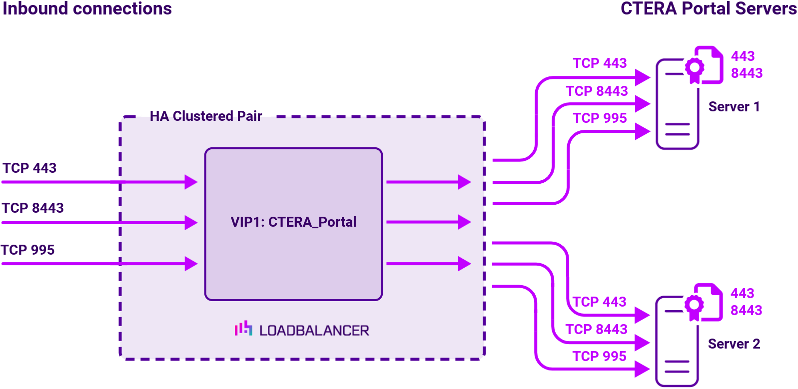
SSL termination on CTERA Portal:
| Ref. | VIP Name | Mode | Port(s) | Persistence Mode | Health Check |
|---|---|---|---|---|---|
| VIP 1 | CTERA_Portal | Layer 7 Reverse Proxy (TCP) | 443,995,8443 | Source IP | HTTPS (GET) |
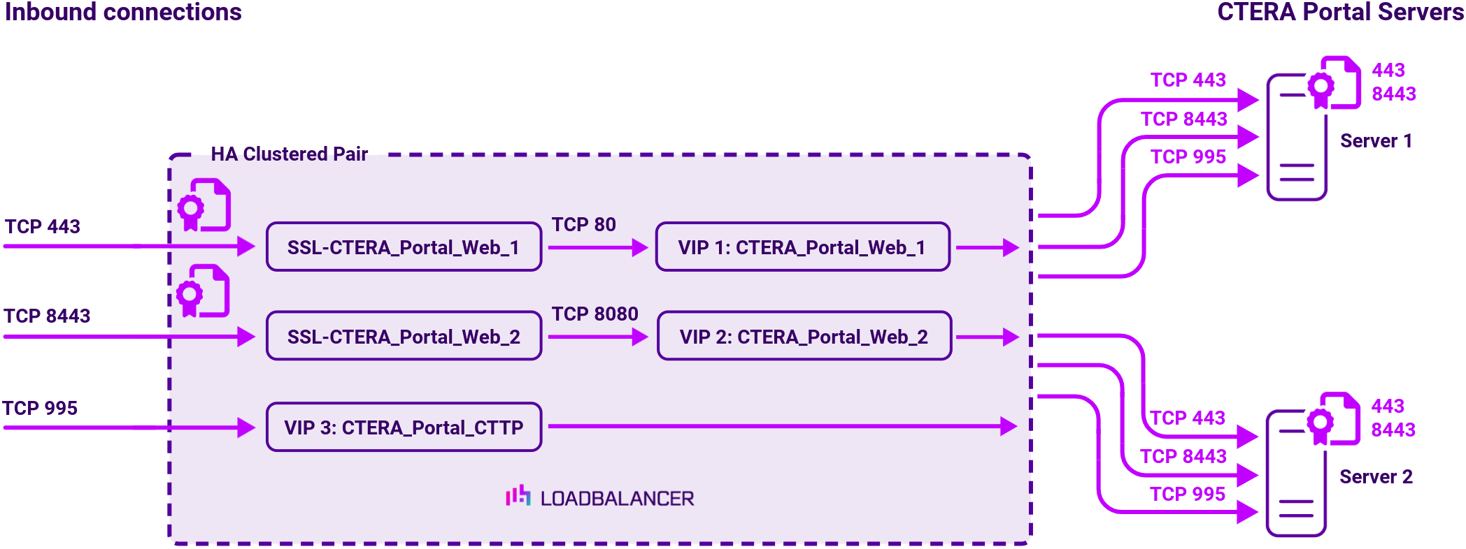
SSL termination on load balancer:
| Ref. | VIP Name | Mode | Port(s) | Persistence Mode | Health Check |
|---|---|---|---|---|---|
| VIP 1 | CTERA_Portal_Web_1 | Layer 7 Reverse Proxy (HTTP) | 80 | Source IP | HTTPS (GET) |
| VIP 2 | CTERA_Portal_Web_2 | Layer 7 Reverse Proxy (HTTP) | 8080 | Source IP | HTTPS (GET) |
| VIP 3 | CTERA_Portal_CTTP | Layer 7 Reverse Proxy (TCP) | 995 | Source IP | Connect to Port |
Load balancing deployment concept
SSL termination on CTERA Portal
SSL termination on load balancer
About Layer 7 Reverse Proxy load balancing
Layer 7 Reverse Proxy uses a proxy (HAProxy) at the application layer. Inbound requests are terminated on the load balancer and HAProxy generates a new corresponding request to the chosen Real Server. As a result, Layer 7 is typically not as fast as the Layer 4 methods.
Layer 7 is typically chosen when enhanced options such as SSL termination, cookie based persistence, URL rewriting, header insertion/deletion etc. are required, or when the network topology prohibits the use of the Layer 4 methods.

Because Layer 7 Reverse Proxy is a full proxy, any server in the cluster can be on any accessible subnet, including across the Internet or WAN.
Layer 7 Reverse Proxy is not transparent by default i.e. the Real Servers will not see the source IP address of the client, they will see the load balancer’s own IP address by default, or any other local appliance IP address if preferred (e.g. the VIP address). This can be configured per Layer 7 VIP.
If required, the load balancer can be configured to provide the actual client IP address to the Real Servers in two ways:
- Either by inserting a header that contains the client’s source IP address, or
- By modifying the Source Address field of the IP packets and replacing the IP address of the load balancer with the IP address of the client.
Layer 7 Reverse Proxy mode can be deployed using either a one-arm or two-arm configuration. For two-arm deployments, eth0 is normally used for the internal network and eth1 is used for the external network, although this is not mandatory.
No mode-specific configuration changes to the load balanced Real Servers are required.
Port translation is possible with Layer 7 Reverse Proxy e.g. VIP:80 → RIP:8080 is supported. You should not use the same RIP:PORT combination for Layer 7 Reverse Proxy VIPs and Layer 4 SNAT mode VIPs because the required firewall rules conflict.