Load balancing Ascom Unite
Updated on February 3, 2026
•
Published on February 2, 2026
Benefits of load balancing Ascom Unite
Load balancing Ascom Unite provides the following key benefits:
- High Availability and fault tolerance: Load balancing is the foundation for a highly available system. In an environment where every alert is critical (like a patient monitoring alarm or a nurse call event), hospitals cannot afford downtime. The load balancer monitors the health of all Ascom Unite servers in the cluster. If one server experiences a failure, needs maintenance, or becomes unresponsive, the load balancer automatically and instantly redirects all incoming traffic and events to the remaining healthy servers. This eliminates a single point of failure, ensuring that the system is always online and that critical alerts are delivered without interruption, which is vital for patient safety and continuous operations.
- Enhanced performance and response times: Ascom Unite integrates data from many source systems (nurse call, patient monitors, lab systems) and manages messages for thousands of users. Load balancing ensures that this high volume of communication is handled efficiently. It distributes the processing load (connecting systems, routing alerts, managing mobile sessions) evenly across multiple servers. This prevents any single server from becoming overwhelmed during peak times. This results in faster processing of events and a more responsive system overall. Clinicians experience minimal latency for receiving critical alerts and sending interactive responses, directly improving workflow efficiency and staff response times.
- Scalability to handle growth and demand: Load balancing allows the Unite platform to grow seamlessly with the demands of the organization, accommodating increases in users, devices, and connected systems. When an organization expands (e.g., adds a new wing, connects new patient monitors, or increases the number of mobile users), new Unite servers can be easily added to the existing cluster. The load balancer automatically recognizes and begins routing traffic to the new servers. This means capacity can be scaled horizontally (more servers added) without interrupting service or requiring a major system overhaul. This future-proofs the investment and ensures consistent performance regardless of traffic volume.
About Ascom Unite
Ascom Unite is a vendor-agnostic, standards-based platform that streamlines workflows by integrating data and events from various source systems (like nurse call and patient monitoring). It then intelligently orchestrates alerts, chats, and tasks for users across all major endpoints, including iOS, Android, and web platforms, as well as specialized devices like DECT phones and the Ascom Myco 4.
The result is a demonstrable improvement in patient/resident satisfaction, equipment uptime, and staff productivity. Unite is versatile, serving industries such as healthcare, hospitality, retail, and high-security facilities. It accepts input from systems using both standard and proprietary protocols (HL7, SMTP, TAP, ESPA, SNPP, etc.).
The ASCOM architecture hierarchy
The systems input layer:
- Ascom Telligence: A Nurse Call system specifically for acute care/hospitals. It includes physical hardware like bedside stations and pillow speakers.
- Ascom teleCARE IP: A Nurse Call and monitoring system typically used in long-term care or senior living.
- Relationship: These act as the source of alarms and data. You would typically deploy one or the other (or both in different wings).
The middleware integration layer:
- Ascom Unite Platform Server: This is the central software engine. It listens to Telligence or teleCARE IP, applies rules (e.g., if a code blue occurs, notify the crash team), and routes that data.
- Unite Axess Server: A specific component within the Unite suite that manages the secure delivery of these messages to smart devices.
The endpoint output layer:
- Unite Axess App: The actual application a nurse carries on their smartphone (like an Ascom Myco or an iPhone) to receive the alerts generated by Telligence or teleCARE.
Why Loadbalancer.org for Ascom Unite?
Loadbalancer’s intuitive Enterprise Application Delivery Controller (ADC) is designed to save time and money with a clever, not complex, WebUI.
Easily configure, deploy, manage, and maintain our Enterprise load balancer, reducing complexity and the risk of human error. For a difference you can see in just minutes.
And with WAF and GSLB included straight out-of-the-box, there’s no hidden costs, so the prices you see on our website are fully transparent.
More on what’s possible with Loadbalancer.org.
How to load balance Ascom Unite
The load balancer can be deployed in four fundamental ways: Layer 4 DR mode, Layer 4 NAT mode, Layer 4 SNAT mode, and Layer 7 Reverse Proxy (Layer 7 SNAT mode).
For Ascom Unite, Layer 4 SNAT and Layer Reverse Proxy is recommended.
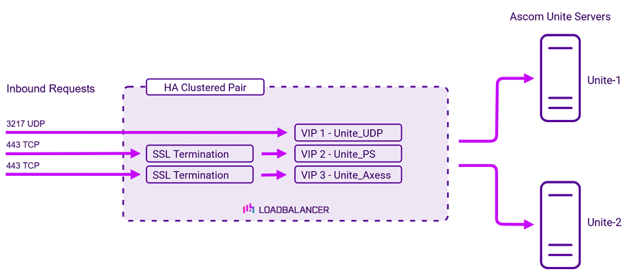
Virtual service (VIP) requirements
To provide load balancing and HA for Ascom Unite, the following VIPs are required:
| Ref. | VIP Name | Mode | Port(s) | Persistence Mode | Health Check |
|---|---|---|---|---|---|
| VIP 1 | Unite_UDP | L4 SNAT UDP | 3217 | Source IP | HTTP GET |
| VIP 2 | Unite_PS | Layer 7 Reverse Proxy | 80 | Source IP | HTTP GET |
| VIP 3 | Unite_Axxes | Layer 7 Reverse Proxy | 8080 | None | HTTP GET |
Please note that Ascom Telligence and Ascom teleCARE can also be load balanced using VIP 1 – Unite_UDP. If this is required, the “Listen on External IP” setting must be enabled and the IP address of the Unite cluster (the VIP address) must be configured within Telligence.
SSL/TLS termination
SSL termination is configured on the load balancer for the following VIPs:
- VIP2 – Unite_PS
- VIP3 – Unite_Axess
This provides a corresponding HTTPS Virtual Service for these VIPs. Certificates in PEM or PFX format can be uploaded to the load balancer.
Load balancing deployment concept
About Layer 4 SNAT mode load balancing
Layer 4 SNAT mode is a high performance solution, although not as fast as Layer 4 NAT mode or Layer 4 DR mode. The image below shows an example network diagram for this mode:

Real Servers in the cluster can be on any accessible network including across the Internet or WAN. Layer 4 SNAT mode is not transparent, an iptables SNAT rule translates the source IP address to be the load balancer rather than the original client IP address. Layer 4 SNAT mode can be deployed using either a one-arm or two-arm configuration.
For two-arm deployments, eth1 is typically used for client side connections and eth0 is used for Real Server connections, although this is not mandatory since any interface can be used for any purpose. Requires no mode-specific configuration changes to the load balanced Real Servers. Port translation is possible with Layer 4 SNAT mode, e.g. VIP:80 → RIP:8080 is supported. You should not use the same RIP:PORT combination for Layer 4 SNAT mode VIPs and Layer 7 Reverse Proxy VIPs because the required firewall rules conflict.
About Layer 7 Reverse Proxy load balancing
Layer 7 Reverse Proxy uses a proxy (HAProxy) at the application layer. Inbound requests are terminated on the load balancer and HAProxy generates a new corresponding request to the chosen Real Server. As a result, Layer 7 is typically not as fast as the Layer 4 methods.
Layer 7 is typically chosen when enhanced options such as SSL termination, cookie based persistence, URL rewriting, header insertion/deletion etc. are required, or when the network topology prohibits the use of the Layer 4 methods.
Because Layer 7 Reverse Proxy is a full proxy, any server in the cluster can be on any accessible subnet, including across the Internet or WAN.
Layer 7 Reverse Proxy is not transparent by default i.e. the Real Servers will not see the source IP address of the client, they will see the load balancer’s own IP address by default, or any other local appliance IP address if preferred (e.g. the VIP address). This can be configured per Layer 7 VIP.
If required, the load balancer can be configured to provide the actual client IP address to the Real Servers in two ways:
- Either by inserting a header that contains the client’s source IP address, or
- By modifying the Source Address field of the IP packets and replacing the IP address of the load balancer with the IP address of the client.
Layer 7 Reverse Proxy mode can be deployed using either a one-arm or two-arm configuration. For two-arm deployments, eth0 is normally used for the internal network and eth1 is used for the external network, although this is not mandatory.
No mode-specific configuration changes to the load balanced Real Servers are required.
Port translation is possible with Layer 7 Reverse Proxy e.g. VIP:80 → RIP:8080 is supported. You should not use the same RIP:PORT combination for Layer 7 Reverse Proxy VIPs and Layer 4 SNAT mode VIPs because the required firewall rules conflict.